Home
> Management
Info >
TEDs & BRDs >
BRDs >
Specifications for Certified BRDs

Specifications
for Certified BRDs
The following
descriptions of specifications for certified BRDs are from
Unofficial compilation of federal relations prepared by the
Southeast Regional Office of NMFS, Appendix D to Part 622
found at the following web site: http://caldera.sero.nmfs.gov/fishery/regs.htm.
All information below includes any changes made in the regulations
up to February 4, 2004.
| Extended
Funnel Bycatch Reduction Device |
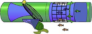
1. Description.
The
extended funnel BRD consists of an extension with large-mesh
webbing in the center (the large-mesh escape section)
and small-mesh webbing on each end held open by a semi-rigid
hoop. A funnel of small-mesh webbing is placed inside
the extension to form a passage for shrimp to the codend.
It also creates an area of reduced water flow to allow
for fish escapement through the large mesh. One side of
the funnel is extended vertically to form a lead panel
and area of reduced water flow. There are two sizes of
extended funnel BRDs, a standard size and an inshore size
for small trawls.
2. Minimum
Construction and Installation Requirements for Standard
Size.
(a)
Extension Material. The small-mesh sections used on both
sides of the large-mesh escape section are constructed
of 1 5/8 inch (4.13 cm), No. 30 stretched mesh, nylon
webbing. The front section is 120 meshes around by 6 1/2
meshes deep. The back section is 120 meshes around by
23 meshes deep.
(b)
Large-Mesh Escape Section. The large-mesh escape section
is constructed of 8 to 10 inch (20.3 to 25.4 cm), stretched
mesh, webbing. This section is cut on the bar to form
a section that is 15 inches (38.1 cm) in length by 95
inches (241.3 cm) in circumference. The leading edge is
attached to the 6 1/2-mesh extension section and the rear
edge is attached to the 23-mesh extension section.
(c)
Funnel. The funnel is constructed of 1 1/2 inch (3.81
cm), stretched mesh, No. 30 depth-stretched and heat-set
polyethylene webbing. The circumference of the leading
edge is 120 meshes and the back edge is 78 meshes. The
short side of the funnel is 34 to 36 inches (86.4 to 91.4
cm) long and the opposite side of the funnel extends an
additional 22 to 24 inches (55.9 to 61.0 cm). The circumference
of the leading edge of the funnel is attached to the forward
small-mesh section three meshes forward of the large-mesh
escape section and is evenly sewn, mesh for mesh, to the
small-mesh section. The after edge of the funnel is attached
to the after small-mesh section at its top and bottom
eight meshes back from the large-mesh escape panel. Seven
meshes of the top and seven meshes of the bottom of the
funnel are attached to eight meshes at the top and bottom
of the small-mesh section, such eight meshes being located
immediately adjacent to the top and bottom centers of
the small-mesh section on the side of the funnel's extended
side. The extended side of the funnel is sewn at its top
and bottom to the top and bottom of the small-mesh section,
extending at an angle toward the top and bottom centers
of the small-mesh section.
(d)
Semi-Rigid Hoop. A 30-inch (76.2-cm) diameter hoop constructed
of plastic-coated trawl cable, swaged together with a
3/8-inch (9.53-mm) micropress sleeve, is installed five
meshes behind the trailing edge of the large-mesh escape
section. The extension webbing must be laced to the ring
around the entire circumference and must be equally distributed
on the hoop, that is, 30 meshes must be evenly attached
to each quadrant.
(e)
Installation. The extended funnel BRD is attached 8 inches
(20.3 cm) behind the posterior edge of the TED. If it
is attached behind a soft TED, a second semi-rigid hoop,
as prescribed in paragraph A.2.(d), must be installed
in the front section of the BRD extension webbing at the
leading edge of the funnel. The codend of the trawl net
is attached to the trailing edge of the BRD.
3. Minimum
Construction and Installation Requirements for Inshore Size.
(a)
Extension Material. The small-mesh sections used on both
sides of the large-mesh escape section are constructed
of 1 3/8 inch (3.5 cm), No. 18 stretched mesh, nylon webbing.
The front section is 120 meshes around by 6 1/2 meshes
deep. The back section is 120 meshes around by 23 meshes
deep.
(b)
Large-Mesh Escape Section. The large-mesh escape section
is constructed of 8 to 10 inch (20.3 to 25.4 cm), stretched
mesh, webbing. This section is cut on the bar to form
a section that is 15 inches (38.1 cm) by 75 inches (190.5
cm) in circumference. The leading edge is attached to
the 6 1/2-mesh extension section and the rear edge is
attached to the 23-mesh extension section.
(c)
Funnel. The funnel is constructed of 1 3/8 inch (3.5 cm),
stretched mesh, No. 18 depth-stretched and heat-set polyethylene
webbing. The circumference of the leading edge is 120
meshes and the back edge is 78 meshes. The short side
of the funnel is 30 to 32 inches (76.2 to 81.3 cm) long
and the opposite side of the funnel extends an additional
20 to 22 inches (50.8 to 55.9 cm). The circumference of
the leading edge of the funnel is attached to the forward
small-mesh section three meshes forward of the large-mesh
escape section and is evenly sewn, mesh for mesh, to the
small-mesh section. The after edge of the funnel is attached
to the after small-mesh section at its top and bottom
eight meshes back from the large-mesh escape panel. Seven
meshes of the top and seven meshes of the bottom of the
funnel are attached to eight meshes at the top and bottom
of the small-mesh section, such eight meshes being located
immediately adjacent to the top and bottom centers of
the small-mesh section on the side of the funnel's extended
side. The extended side of the funnel is sewn at its top
and bottom to the top and bottom of the small-mesh section,
extending at an angle toward the top and bottom centers
of the small-mesh section.
(d)
Semi-Rigid Hoop. A 24-inch (61.0-cm) diameter hoop constructed
of plastic-coated trawl cable, swaged together with a
3/8-inch (9.53-mm) micropress sleeve, is installed five
meshes behind the trailing edge of the large mesh section.
The extension webbing must be laced to the ring around
the entire circumference and must be equally distributed
on the hoop, that is, 30 meshes must be evenly attached
to each quadrant.
(e)
Installation. The extended funnel BRD is attached 8 inches
(20.3 cm) behind the posterior edge of the TED. If it
is attached behind a soft TED, a second semi-rigid hoop,
as prescribed in paragraph A.3.(d), must be installed
in the front section of the BRD extension webbing at the
leading edge of the funnel. The codend of the trawl net
is attached to the trailing edge of the BRD.
|
| Expanded
Mesh Bycatch Reduction Device |
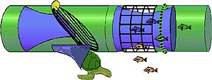
1. Description,
Construction, and Installation.
The
expanded mesh BRD is constructed and installed exactly
the same as the standard size extended funnel BRD above,
except that one side of the funnel is not extended to
form a lead panel.
|
| Fisheye
Bycatch Reduction Device |
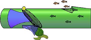
1. Description.
The
fisheye BRD is a cone-shaped rigid frame constructed from
aluminum or steel rod of at least 1/4 inch diameter, which
is inserted into the codend to form an escape opening.
Fisheyes of several different shapes and sizes have been
tested in different positions in the codend.
2. Minimum
Construction and Installation Requirements.
The
fisheye has a minimum opening dimension of 5 inches (12.7
cm) and a minimum total opening area of 36 square inches
(91.4 square centimeters). The fisheye must be installed
at the top center of the codend of the trawl to create
an opening in the trawl facing in the direction of the
mouth of the trawl no further forward than 11 ft (3.4
m) from the codend drawstring (tie-off rings) or 70 percent
of the distance between the codend drawstring and the
forward edge of the codend, excluding any extension, whichever
is the shorter distance. In the Gulf EEZ only, when the
fisheye BRD is installed in this position, no part of
the lazy line attachment system (i.e., any mechanism,
such as elephant ears or choker straps, used to attach
the lazy line to the codend) may overlap the fisheye escape
opening when the fisheye is installed aft of the attachment
point of the codend retrieval system.
|
|
Gulf fisheye |
1.
Description.
The
Gulf fisheye BRD is a cone-shaped rigid frame constructed
from aluminum or steel that is inserted into the top center
of the codend, or is offset not more than 15 meshes perpendicular
to the top center of the codend, to form an escape opening.
2. Minimum
Construction and Installation Requirements.
The
Gulf fisheye BRD is a cone-shaped rigid frame constructed
of aluminum or steel rods. The rods must be at least 1/4-inch
(6.35-mm) in diameter. Any dimension of the escape opening
must be at least 5.0 inches (12.7 cm), and the total escape
opening area must be at least 36.0 square inches (232.3
square centimeters). The Gulf fisheye must be installed
in the codend of the trawl to create an escape opening
in the trawl, facing in the direction of the mouth of
the trawl, no further forward than 12.5 ft (3.81 m) and
no less than 8.5 ft (2.59 m) from the codend tie-off rings.
When installed in this position, no part of the lazy line
attachment system (i.e., any mechanism, such as elephant
ears or choker straps, used to attach the lazy line to
the codend) may overlap the fisheye escape opening when
the fisheye is installed aft of the attachment point of
the codend retrieval system. The Gulf fisheye BRD may
not be offset more than 15 meshes perpendicular to the
top center of the codend.
|
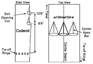
Jones-Davis
Bycatch Reduction Device
|
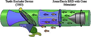
1. Description.
The
Jones-Davis BRD is similar to the expanded mesh and the
extended funnel BRDs except that the fish escape openings
are windows cut around the funnel rather than large-mesh
sections. In addition, a webbing cone fish deflector is
installed behind the funnel.
2. Minimum
Construction and Installation Requirements.
The
Jones-Davis BRD must contain all of the following.
(a)
Webbing extension. The webbing extension must be constructed
from a single piece of 1 5/8-inch (3.5-cm) stretch mesh
number 30 nylon 42 meshes by 120 meshes. A tube is formed
from the extension webbing by sewing the 42-mesh side
together.
(b)
A 28-inch (71.1-cm) cable hoop. A single hoop must be
constructed of 1/2-inch (1.3-cm) steel cable 88 inches
(223.5 cm) in length. The cable must be joined at its
ends by a 3-inch (7.6-cm) piece of 1/2-inch (1.3-cm) aluminum
pipe and pressed with a 3/8-inch (0.95-cm) die to form
a hoop. The inside diameter of this hoop must be between
27 and 29 inches (68.6 and 73.7 cm). The hoop must be
attached to the extension webbing 17 1/2 meshes behind
the leading edge. The extension webbing must be quartered
and attached in four places around the hoop, and every
other mesh must be attached all the way around the hoop
using number 24 twine or larger. The hoop must be laced
with 3/8-inch (0.95-cm) polypropylene or polyethylene
rope for chaffing.
(c)
A 24-inch (61.0-cm) hoop. A single hoop must be constructed
of either number 60 twine 80 inches (203.2 cm) in length
or 3/8-inch (0.95-cm) steel cable 75 1/2 inches (191.8
cm) in length. If twine is used, the twine must be laced
in and out of the extension webbing 39 meshes behind the
leading edge, and the ends must be tied together. If cable
is used, the cable must be joined at its ends by a 3-inch
(7.6-cm) piece of 3/8-inch (0.95-cm) aluminum pipe and
pressed together with a 1/4-inch (0.64-cm) die to form
a hoop. The inside diameter of this hoop must be between
23 and 25 inches (58.4 and 63.4 cm). The hoop must be
attached to the extension webbing 39 meshes behind the
leading edge. The extension webbing must be quartered
and attached in four places around the hoop, and every
other mesh must be attached all the way around the hoop
using number 24 twine or larger. The hoop must be laced
with 3/8-inch (0.95-cm) polypropylene or polyethylene
rope for chaffing.
(d)
Funnel. The funnel must be constructed from four sections
of 1 1/2-inch (3.8-cm) heat-set and depth-stretched polypropylene
or polyethylene webbing. The two side sections must be
rectangular in shape, 29 1/2 meshes on the leading edge
by 23 meshes deep. The top and bottom sections are 29
1/2 meshes on the leading edge by 23 meshes deep and tapered
1 point 2 bars on both sides down to 8 meshes across the
back. The four sections must be sewn together down the
23-mesh edge to form the funnel.
(e)
Attachment of the funnel in the webbing extension. The
funnel must be installed two meshes behind the leading
edge of the extension starting at the center seam of the
extension and the center mesh of the funnel's top section
leading edge. On the same row of meshes, the funnel must
be sewn evenly all the way around the inside of the extension.
The funnel's top and bottom back edges must be attached
one mesh behind the 28-inch (71.1-cm) cable hoop (front
hoop). Starting at the top center seam, the back edge
of the top funnel section must be attached four meshes
each side of the center. Counting around 60 meshes from
the top center, the back edge of the bottom section must
be attached 4 meshes on each side of the bottom center.
Clearance between the side of the funnel and the 28-inch
(71.1-cm) cable hoop (front hoop) must be at least 6 inches
(15.2 cm) when measured in the hanging position.
(f)
Cutting the escape openings. The leading edge of the escape
opening must be located within 18 inches (45.7 cm) of
the posterior edge of the turtle excluder device (TED)
grid. The area of the escape opening must total at least
864 square inches(5,574.2 square centimeters). Two escape
openings 10 meshes wide by 13 meshes deep must be cut
6 meshes apart in the extension webbing, starting at the
top center extension seam, 3 meshes back from the leading
edge and 16 meshes to the left and to the right (total
of four openings). The four escape openings must be double
selvaged for strength.
(g)
Alternative Method for Constructing the Funnel and Escape
Openings. The following method for constructing the funnel
and escape openings may be used instead of the method
described in paragraphs F.2.d., F.2.e., and F.2.f. of
this section. With this alternative method, the funnel
and escape openings are formed by cutting a flap in each
side of the extension webbing; pushing the flaps inward;
and attaching the top and bottom edges along the bars
of the extension webbing to form the v-shape of the funnel.
Minimum requirements applicable to this method include:
(1) The funnel's top and bottom back edges must be attached
one mesh behind the 28-inch (71.1-cm) cable hoop (front
hoop); (2) clearance between the side of the funnel and
the 28-inch (71.1-cm) cable hoop (front hoop) must be
at least 6 inches (15.2 cm) when measured in the hanging
position; (3) the leading edge of the escape opening must
be located within 18 inches (45.7 cm) of the posterior
edge of the turtle excluder device (TED) grid; and, (4)
the area of the escape opening must total at least 864
square inches (5,574.2 square centimeters). To construct
the funnel and escape openings using this method, begin
3 1/2 meshes from the leading edge of the extension, at
the top center seam, count over 18 meshes on each side,
and cut 13 meshes toward the back of the extension. Turn
parallel to the leading edge, and cut 26 meshes toward
the bottom center of the extension. Next, turn parallel
to the top center seam, and cut 13 meshes forward toward
the leading edge, creating a flap of webbing 13 meshes
by 26 meshes by 13 meshes. Lengthen the flap to 18 meshes
by adding a 4 1/2-mesh by 26-mesh rectangular section
of webbing to the 26-mesh edge. Attach the 18-mesh edges
to the top and bottom of the extension by sewing 2 bars
of the extension to 1 mesh on the flap in toward the top
center and bottom center of the extension, forming the
exit opening and the funnel. Connect the two flaps together
in the center with a 7-inch piece of number 42 twine to
allow adequate clearance for fish escapement between the
flaps and the side openings. On each side, sew a 6-mesh
by 10 1/2-mesh section of webbing to 6 meshes of the center
of the 26-mesh cut on the extension and 6 meshes centered
between the 13-mesh cuts 3 1/2 meshes from the leading
edge. This forms two 10-mesh by 13-mesh openings on each
side.
(h)
Cone fish deflector. The cone fish deflector is constructed
of 2 pieces of 1 5/8-inch (4.13-cm) polypropylene or polyethylene
webbing, 40 meshes wide by 20 meshes in length and cut
on the bar on each side forming a triangle. Starting at
the apex of the two triangles, the two pieces must be
sewn together to form a cone of webbing. The apex of the
cone fish deflector must be positioned within 10-14 inches
(25.4-35.6 cm) of the posterior edge of the funnel.
(i)
11-inch (27.9-cm) cable hoop for cone deflector. A single
hoop must be constructed of 5/16-inch (0.79-cm) or 3/8-inch
(0.95-cm) cable 34 1/2 inches (87.6 cm) in length. The
ends must be joined by a 3-inch (7.6-cm) piece of 3/8-inch
(0.95-cm) aluminum pipe pressed together with a 1/4-inch
(0.64-cm) die. The hoop must be inserted in the webbing
cone, attached 10 meshes from the apex and laced all the
way around with heavy twine.
(j)
Installation of the cone in the extension. The cone must
be installed in the extension 12 inches (30.5 cm) behind
the back edge of the funnel and attached in four places.
The midpoint of a piece of number 60 twine 4 ft (1.22
m) in length must be attached to the apex of the cone.
This piece of twine must be attached to the 28-inch (71.1-cm)
cable hoop at the center of each of its sides; the points
of attachment for the two pieces of twine must be measured
20 inches (50.8 cm) from the midpoint attachment. Two
8-inch (20.3-cm) pieces of number 60 twine must be attached
to the top and bottom of the 11-inch (27.9-cm) cone hoop.
The opposite ends of these two pieces of twine must be
attached to the top and bottom center of the 24-inch (61-cm)
cable hoop; the points of attachment for the two pieces
of twine must be measured 4 inches (10.2 cm) from the
points where they are tied to the 11-inch (27.9-cm) cone
hoop.
Diagrams
provided by Dr. Steve Branstetter, Fishery Management
Specialist, NMFS SERO, St. Petersburg, FL
Download:
BRDspecs.pdf
(115KB file) |
|
|